 |
| Music |
| Computing |
| Info Arch |
| Theory |
| Practice |
| Glossary |
| Index |
Unified Modeling Language |
|
A set of graphical notations that can be used to define abstract models of systems. UML2.0 is the standard set of diagrams used in software development and hence has been adopted in many other fields
History
During the late 1980s and early 1990s a wide variety of different schematic diagrams were employed in software development. Many of these approaches shared common concepts but presented them in incompatible ways. This plethora of distinct pictures caused confusion and over the course of a few years the main elements were consolidated into the Unified Modeling Language. Since the mid 1990s this graphical language has been refined to cover a number of topics "near" the domain of software development.
Relation to Information Architecture
While the early versions of this "graphical language" were closely tied to "Object Oriented Development" the most recent variants, especially UML 2.0 and later, have enabled a much wider discussion. In recent times UML diagrams have become the de-facto standard for topics such as enterprise architecture, business process description and user interface design.
Where a suitable UML diagram exists it should be adopted by the Information Architect, this ensures the widest possible audience for the artifacts created. There is a note of caution here, any diagram that looks "UMLish" but uses UML concepts in ways that are unfamiliar to the stakeholders will just confuse the issue. Where the strict UML concepts have been adjusted to meet other needs this should be flagged, either visually by using obviously distinct graphical elements, or as a set of notes with the diagrams to explain the differences. This does mean that architects, who often do not have a software development background, must understand the original intent and nuances of the diagrams they use.
Diagram Types
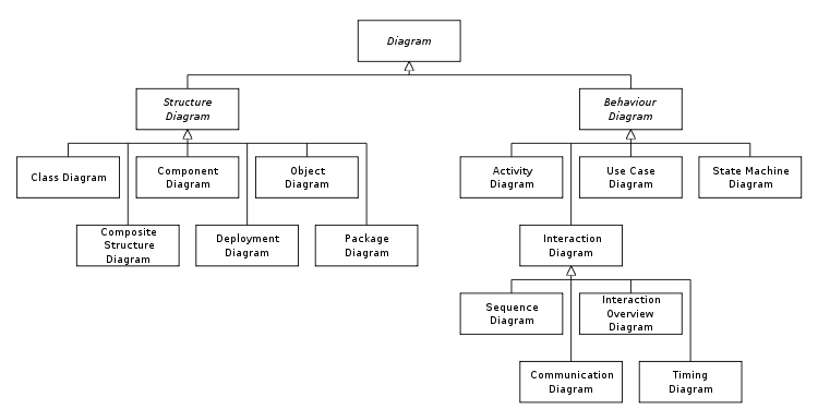
UML 2.0 has 13 types of diagrams divided into the three categories shown above. Six diagram types represent the structure, seven represent general types of behaviour, including four that represent different aspects of interactions.
UML Structure Diagrams
Structure diagrams emphasize what things must be in the system being modeled:
- UML Class Diagram: describes the structure of a system by showing the system's classes, their attributes, and the relationships among the classes.
- UML Component Diagram: depicts how a software system is split up into components and shows the dependencies among these components.
- UML Composite Structure Diagram: describes the internal structure of a class and the collaborations that this structure makes possible.
- UML Deployment Diagram: serves to model the hardware used in system implementations, and the execution environments and artifacts deployed on the hardware.
- UML Object Diagram: shows a complete or partial view of the structure of a modeled system at a specific time.
- UML Package Diagram: depicts how a system is split up into logical groupings by showing the dependencies among these groupings.
UML Behaviour Diagrams
Behaviour diagrams emphasise what must happen in the system being modeled:
- UML Activity Diagram: represents the business and operational step-by-step workflows of components in a system. An activity diagram shows the overall flow of control.
- UML State Machine Diagram: standardized notation to describe many systems, from computer programs to business processes.
- UML Use Case Diagram: shows the functionality provided by a system in terms of actors, their goals represented as use cases, and any dependencies between them.
UML Interaction Diagrams
Interaction diagrams, a subset of behaviour diagrams, emphasize the flow of control and data among the things in the system being modeled:
- UML Communication Diagram: shows the interactions between objects or parts in terms of sequenced messages. They represent a combination of information taken from Class, Sequence, and Use Case Diagrams describing both the static structure and dynamic behaviour of a system.
- UML Interaction Overview Diagram: are a type of activity diagram in which the nodes represent interaction diagrams.
- UML Sequence Diagram: shows how objects communicate with each other in terms of a sequence of messages. Also indicates the lifespans of objects relative to those messages.
- UML Timing Diagram: are a specific type of interaction diagram, where the focus is on timing constraints.
External Resources
Links to this page
The following pages link to here: Concept Map, Data Modeling Language, IA Rendition, UML Activity Diagram, UML Behaviour Diagrams, UML Class Diagram, UML Communication Diagram, UML Component Diagram, UML Composite Structure Diagram, UML Deployment Diagram, UML Interaction Overview Diagram, UML Object Diagram, UML Package Diagram, UML Sequence Diagram, UML State Machine Diagram, UML Structure Diagrams, UML Timing Diagram, UML Use Case Diagram