 |
| Music |
| Computing |
| Info Arch |
| Theory |
| Practice |
| Glossary |
| Index |
Karnaugh Map |
|
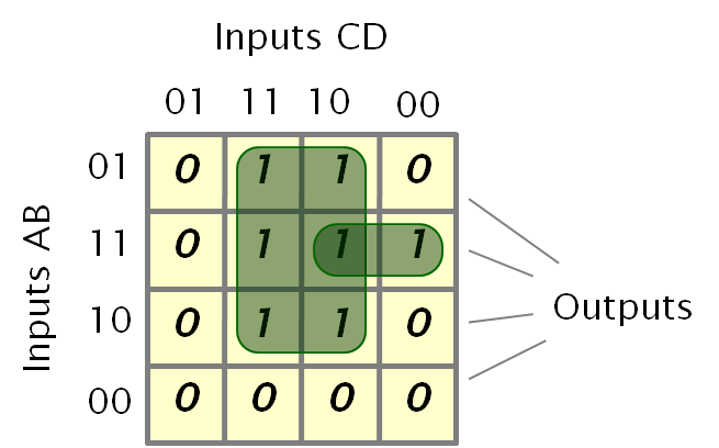
A diagram that documents the way a system's output changes as the inputs are varied. The various inputs are arranged in a "Gray Code" sequence, so that only one element changes between squares. In the example above the four inputs ABCD define the output state, the output in this case is either 1 or 0 (in the set or not).
Classification
In the above example the boolean logic can be implemented in a variety of ways. The green regions show that one expression would be:
output = (C and (A or B)) or ((A and B) and (not D))
Combining a few large regions, rather than many small ones, makes the expression simpler and often helps illuminate relationships between the inputs. For many types of classification this approach helps clarify some of the details.
Race Conditions
Any permitted change can be considered as a set of "jumps" to adjacent squares. If the possible routes to a square lead to different results then a race condition exists and the system should be redesigned either to eliminate the inconsistency or to ensure that the inputs cannot vary in that way.
When creating the areas that define a function race conditions often occur when moving into or out of the regions. If, for example we were to define the function as:
output = (C and (A or B)) or ((A and B) and ((not D) and (not C)))
Then the smaller area would just enclose a single output square and the transition between the two would often generate a race condition in the resulting circuit.
Links to this page
The following pages link to here: Race Condition